I will solve Some problems of simple gas turbine power plant with the students during this power plant engineering lecture.
This lecture on Gas Turbine Power Plant includes:
1) Calculation of thermal efficiency in gas turbine power plant
2) Calculation of work ratio of gas turbine power plant
3) Calculation of pressure ratio in gas turbine power plant
Saturday, 27 February 2021
Determine Thermal Efficiency, Work ratio, Pressure ratio of Gas Turbine Power Plant

Saturday, 9 January 2021
Condition of Maximum Work done in Brayton Cycle, Maximum Efficiency, work Ratio and Air Rate for simple gas Turbine
In this lecture on Power Plant engineering you will Learn:
(1) Condition of maximum work
(2) Joule cycle Maximum Thermal Efficiency derivation
(3) Work Ratio of Gas Turbine: It is the ratio of net work produced by the plant to the turbine work. The work ratio represents the amount of net work generated by the gas turbine plant per unit turbine work output.
The work ratio increases with an increase in turbine inlet temperature, a decrease in compressor inlet temperature, and a decrease in the pressure ratio of the cycle. the compressor inlet temperature is always atmospheric temperature particularly in the open cycle and turbine inlet temperature is limited by metallurgical consideration. The highest temperature ever used for a gas turbine power plant is about 1000 k.
(4) Air rate: The size of the gas turbine plant is dependent upon the rate of air flow in relation to net output work. Compact gas turbine plant has a lower value of air rate. Air rate is expressed as kg of air per kWhr.
(1) Condition of maximum work
(2) Joule cycle Maximum Thermal Efficiency derivation
(3) Work Ratio of Gas Turbine: It is the ratio of net work produced by the plant to the turbine work. The work ratio represents the amount of net work generated by the gas turbine plant per unit turbine work output.
The work ratio increases with an increase in turbine inlet temperature, a decrease in compressor inlet temperature, and a decrease in the pressure ratio of the cycle. the compressor inlet temperature is always atmospheric temperature particularly in the open cycle and turbine inlet temperature is limited by metallurgical consideration. The highest temperature ever used for a gas turbine power plant is about 1000 k.
(4) Air rate: The size of the gas turbine plant is dependent upon the rate of air flow in relation to net output work. Compact gas turbine plant has a lower value of air rate. Air rate is expressed as kg of air per kWhr.
Saturday, 23 May 2020
Ideal Brayton cycle efficiency for gas turbine with P V and T S diagram
The ideal cycle for gas turbine is Brayton or jule cycle. The Brayton cycle has two constant pressure and two isentropic processes. In this video, i have explained PV and TS diagram of Brayton cycle. This video will show you the Analysis of Brayton cycle, and at the end of the video, you will get the equation to find the thermal efficiency of a simple gas turbine power plant. The analysis of Brayton is carried out with the following assumptions: 1) Compression and expansion are isentropic. 2) Pressure losses in the system are neglected. 3) Heat losses in the system are neglected. 4) specific heat of working fluid is taken constant throughout the cycle. Considering the 1kg of working fluid.
Saturday, 4 January 2020
Gas Turbine Engine Fuel
The gas turbine engine can be operated with gas, liquid and solid fuels. However, this statement is not true for all gas turbine engine. The selection of fuel for gas turbine is dependent on type of cycle, size and length of engine and application of gas turbine engine. The most important requirement of a gas turbine fuel are
(1) composition should provide proper combustion and rapid burning,
(2) the product of combustion should contain a minimum of mater which might get deposited on the turbine blades or the heat exchanger,
(3) highest heating value per kg or m^3 volume specially for aircraft engine.
The modern gas turbine are normally operated on the following fuels:
a) Gaseous fuels: Natural gas, Blast furnace gas, Producer gas, Sewage gas, etc.…
b) Liquid fuels: Kerosene, Gasoline, Residual oils, etc.…
c) Solid Fuels: Coal
The solid fuel (Coal) is normally used in closed cycle gas turbine. The main problem with using solid fuel in the case of open cycle plans is of reducing the level of flyash in the gases leaving the combustion chamber so that the blades of the turbines are not eroded. For this, it is necessary to ensure proper cleaning of the combustion gases from fine ash and dust. Before the gas enters the turbine, it is purified with help of the various flyash collectors. The use of coal as a fuel of open cycle gas turbine is under the development. Coal is burnt in two methods. In the first method, the coal is completely or partially gasified and fuel gas produced is supplied to gas turbine combustor. In other method, pressurized bubbling or circulating fluidized bed, where fuel gas, after it is adequately filtered, expands in the gas turbine. Coal is usually considered as a gas turbine fuel in combined cycle power plant.
Liquid oil like kerosene, gasoline, etc. are easily used in a gas turbine combustor. Residual oils can be used as fuel in gas turbine. If the viscosity of the oil is high, some heating arrangement required.
Saturday, 12 October 2019
What are the pros and cons of using closed cycle gas turbines?
As we know that in open cycle gas turbine power plant, the fuel is mixed with air in the combustion chamber and the combustion gases are expanded in the gas turbine which causes erosion and corrosion of turbine blades and therefore it is necessary to use fuel superior quality in the combustion chamber in order to minimize erosion and corrosion. This negative effect overcome in case closed gas turbine power plant. In the closed gas turbine power plant, the same air or working fluid is circulated over and over again. The working medium is not mixed with fuel, but it is heated by the burning of fuel in a separate supply of air in the combustion chamber and the transferring this heat to the working fluid which passes through tubes fitted in the combustion chamber. The working fluid does not come in to direct contact with products of combustion. The other disadvantage of open cycle gas turbine gas turbine plant is that the turbine exhaust is discharged into the atmosphere resulting in rejection of heat of exhaust gases to the atmosphere. In case of closed cycle these heat are recovered in a heat exchanger or recooler.
The working fluid (air or any other suitable gas such as helium, argon, hydrogen, and neon) coming out from compressor is heated in the heat exchanger (heater) by an external source at constant pressure. The high temperature and high pressure air coming out from the external heater is passed through the gas turbine. The working fluid coming out from the turbine is cooled to its original temperature in the heat exchanger (cooler) using external heating source before passing in the compressor. In the closed cycle, the working fluid is continuously circulated through compressor, cooler, heater and turbine without its change of phase, the required heat addition and rejection taken place in the heater and cooler respectively.
The performance characteristics, component elements and analysis for open cycle apply equally as well as to the closed cycle gas turbine.
Advantages of closed cycle over open cycle:
1) In the closed cycle gas turbine, the working medium is heated externally and the fuel does not mix with it, hence any inexpensive solid fuel such as coal can be used to heat the working fluid. Also need for filtration of the incoming air is completely eliminated.
2) They are kept free from product of combustion. Hence absence of corrosion and abrasion of the interiors of turbines and compressors extends the life of the plant and maintains the efficiency of the plant constant throughout its life.
3) The working medium is at relatively high internal pressure. So, specific volume is less and the dimensions of the compressors and turbines can be reduced and the maximum unit capacity can be increased.
4) A working medium such as helium, argon, hydrogen, neon may be used which has very good physical properties compared to those of air. For example thermal conductivity of hydrogen is about 6.8 times that of air and therefore require smaller heat exchanger.
5) The closed cycle can be operated with highest efficiencies in comparison to open cycle plants at an equal initial temperature of working fluid.
6) The power output at constant speed can be varied by adding or substracting the working fluid and thus altering the weight of the charge. This gives improved part load efficiency as compared to open cycle gas turbine.
7) High heat transfer can be possible
Disadvantages of closed cycle:
1) In closed cycle gas turbine considerable quantity of cooling water is required.
2) Heat addition to the working medium takes place through heat exchanger, hence full heat of fuel fired is not utilized.
3) Additional equipments such as externally fired heater, cooler are required, the plant and its operation makes additional complexity.
Thursday, 28 February 2019
Essential hydraulics fluid power basic
FLUID POWER SYSTEM
Fluid power system is power transmission system in which, the transmission of power takes place by means of “oil under pressure” or “compressed air”.
If “oil under pressure” is used in the system for power transmission, then the system is called “hydraulic system”.
If “compressed air” is used in the system for the power transmission then the system is called “pneumatic system”.
If large force and low speed is needed, then hydraulic system should be selected.
Because, oil is incompressible. Its volume will not change with increase in pressure. Pressure can be increased to any amount, nothing happens to volume of oil.
More the pressure of oil, more will be the force developed.
Hydraulic systems are slower in operation because, oil has more viscosity. Oil can not flow fast as compressed air.
If less force and higher speed is required, then pneumatic system should be selected.
As air is compressible in nature, it can not be pressurized to large amount of pressure. Since the pressure of compressed air is less (about 10 bar), force developed is also less.
Pneumatic systems are faster in operation because, air has very less viscosity. It can flow very quickly. Air rushes in to the cylinder once the valve is opened and within no time, the cylinder extends.
If compressed air is readily available in the industry, then pneumatic system is preferred.
In many industries, air compressed plant is already installed, as compressed air is needed for different processes. In such case, we can use the compressed air for operating pneumatic system.
Advantage of fluid power system:
1. Fluid power system avoids mechanical linkage (such as belts pulley, chains, sprockets, gears etc.) to a greater extent.
2. Hence, breakdowns are reduced and production will increase.
3. “design and construction” of fluid power system is easy, simple and compact, as pipes are flexible, can be bent and accommodated in the available space.
4. Automatic and safety circuits are possible, which is very important to increase rate of production and safety to avoid accidents.
5. Fluid power system are more flexible to cope-up with the design changes. Any modification in design can easily in the existing and the fluid power system.
6. Vibration and noise, wear ad ear etc. are reduced, as the mechanical linkages are replaced by the pipes.
7. If overloaded, the system stalls, the system starts working once the load is reduced.
8. Maintenance, servicing, lubrication etc. are simple and easy.
Sunday, 25 March 2018
What can a jobless mechanical engineering fresher in India do to get hired if he has a good knowledge of AutoCAD, catia and ansys?

well, before i give answer of question, i want to say that Mechanical engineer are awesome. being Mechanical engineer is not a joke. only smart and hard working person can become an engineer. and you have good knowledge of AutoCAD, catia and ansys which is your plus point. but you want job. and before you get job all you have to take care is “Apply to company only if they really require your expertise”. other wise you have some other option such as:
- go to foreign and use your skill to help those companies which really require your skills.
- prepare for government exams and you are engineer so you have habit of studying hard so it will be very easy as compare to other graduates to crack exam.
- open classes for engineering students and start teaching AutoCAD, catia & ansys and also start taking orders from other industries for designing.
- analyze your situation and situation of market by using your operation research skills which you already studied during your engineering and take decision. you should proud of having knowledge of everything and being scientist of Mechanism.
Monday, 19 February 2018
open cycle gas turbine power plant
A simple cycle gas turbine consists of a (1) compressor, (2)
combustion chamber and (3) gas turbine.
In the open cycle gas turbine, ambient air enters at the
compressor and after the compression of air, fuel is burned in the air itself
to raise it to high temperature and then product of combustion are passed on to
the turbine for expansion. After delivering the work combustion products are
finally rejected to atmosphere. In the open cycle the working medium is
continuously replaced by fresh air and fuel. It works on the joule cycle and
Brayton cycle.
The air is sucked in by the compressor from the atmosphere
through the filter which removes the dust from the air. The rotary blades of
the compressor push the air between the stationary blades to raise its pressure
to 4-5 atmosphere. Hence the air is available at high pressure at output of the
compressor. Then high pressure air passes through combustion chamber, in which
heat added to the air at constant pressure by burning the fuel and raises
temperature (about 1650) of working medium. This high temperature must be
brought down to the level so that the thermal stresses in the turbine blades do
not become excessive. This is achieved by allowing the reminder air to enter
the combustion chamber at downstream to mix and cool down the combustion gases.
The products of combustion comprising of mixture of gases at high pressure and
temperature are passes through the gas turbine. These gases in passing over the
turbine blades expand and thus result in motion of rotor and finally discharged
to the atmosphere at the temperature about 540.
Advantage of open cycle:
I.
Simplicity: There are only few rotating parts as
turbine, compressor and gear train driving the auxilliaries. Hence problem of
vibration and lubrication is not so severe. The ignition system is also simple
compared to closed cycle.
II.
Flexibility: since different processes within
the cycle take part in separate components, a great variety in the arrangement
of the system is possible.
III.
Low weight and size: The weight in kg. per KW
developed is less.
IV.
Independent system: Open cycle gas turbine power
plant, except those having intercooler, does not require cooling water. There
fore the plant is independent of cooling medium and becomes self-contained.
V.
Fuels: Almost any hydrocarbon fuel from high
octane gasoline to heavy diesel oils including some solid fuels can be burned
in the combustion chamber.
VI.
Warm-up time: After the turbine has been brought
up to speed by the starting motor and the fuel ignited the gas turbine will
accelerate from cold start to full load without a warm up time. This is
particularly important in stand by emergency plants.
Disadvantage of open cycle:
I.
Part load performance: The part load efficiency
of the open cycle plant decreases rapidly as the considerable percentage of
power developed by the turbine, is used to drive the compressor. Also, the
system is sensitive to the changes in components efficiency.
II.
Sensitivity: Since system sensitive to the
component efficiency, particularly that of compressor. The efficiency of
compressor is affected by change in the atmospheric conditions such as
temperature ad humidity of air at the inlet and foreign matter contained in the
air.
III.
High air rate: The simple open cycle gas turbine
has a very high air rate as compared to other prime movers. However, the air
rate may be lowered by intercooling and reheating.
IV.
Erosion and corrosion: The working fluid is
mixture of air and fuel. Since air contains dirt being deposited on the
compressor blades. Due to carbon and other foreign deposits from combustion in
the combustion chamber, turbine and regenerator, it is necessary that the dust
should be prevented from entering into the compressor in order to minimized
erosion and depositions on the blades and passages of the compressor and
turbine.
V.
In the simple open cycle, the turbine exhaust is
discharged into atmosphere. Since turbine exhaust contain large amount of heat
resulting in loss of heat.
Friday, 16 February 2018
Classification of Gas Turbine Power Plant
The gas turbine can be classified as follows:
1) According to types of combustion process
I.
Constant volume or explosion type gas turbine:
This type of Gas turbine works on Atkinson cycle in which combustion of air
fuel mixture is takes place at constant volume, hence air and fuel mixture
should be isolated from compressor. This is possible by valves in the
combustion chamber, resulting in an intermittent combustion which inherently
impairs smooth running of machine. This type of turbine has better thermal
efficiency than a constant pressure cycle gas turbine. The main disadvantages
of this type of gas turbine is that complexity in mechanical system and
pressure difference and velocity of hot gases are not constant, so turbine
speed fluctuates. The constant volume combustion type gas turbine is not
popular in practical use. The constant volume gas turbines are absolute in use.
II.
Constant pressure or continuous combustion type
gas turbine: This type of gas turbine works on Brayton cycle in which
combustion of air fuel mixture is takes place at constant pressure.
2) According to direction of flow
I.
Axial flow gas turbine
II.
Radial flow gas turbine.
3) According to action of expanding gases
I.
Impulse gas turbine
II.
Impulse- Reaction gas turbine
4) According to path of working substance
I.
Open cycle gas turbine plants: In the open cycle
gas turbine, ambient air enters at the compressor and after the compression of
air, fuel is burned in the air itself to raise it to a high temperature and
then product of combustion is passed on to the turbine for expansion and which
after delivering the work are finally ejected to atmosphere. In the open cycle
the working medium is continuously replaced by fresh air and fuel.
II.
Closed cycle gas turbine plants: In the closed
cycle gas turbine power plant, the same air or the working fluid is circulated
over and over again. The working medium is not mixed with fuel, but it is
heated by the burning of fuel in separate supply of air in the combustion
chamber and transferring this heat to the working fluid which passes through
tubes fitted in the combustion chamber. The working fluid does not come into
direct constant with product of combustion.
III.
Semi-closed cycle gas turbine plants:
Semi-closed cycle gas turbine plant is combination of open and closed cycle, in
which some part of working fluid is recirculated to the plant and another part
of working fluid flows into and from the atmospheric air.
5) According to thermodynamic cycle
I.
Simple cycle
II.
Simple cycle with intercooling: in which the air
is cooled between stages of compression.
III.
Simple cycle with regeneration: in which the air
after compression is heated with help of exhaust gases coming from turbine.
IV.
Simple cycle with reheating: in which combustion
products (gases) after part of expansion in high pressure turbine is reheated
in second combustion chamber and then it is expanded in the low pressure turbine.
V.
Simple cycle with intercooling, regeneration and
reheating.
6) According to shaft configuration
I.
Single shaft engine: - Examples: Turbojet
engine, Turboshaft engine.
II.
Multi-shaft engine: - Example: Two shaft engine
with power turbine, Turbojet engine, industrial slit shaft engine, Twin-spool
engine.
7) According to applications
I.
Power or industrial gas turbines
II.
Aviation or aircraft turbines
Monday, 12 February 2018
What is Deburring?
What is Deburring?
What is a burr?
During most machining processes, work pieces become burred, and sharp edges or material compression occurs.This effects the quality of the part and can create a potential sources of error during the assembly process.
What is burr and how does it occur?
1) During stamping, fineblanking or forming
2) During casting, sinter and molding of material
3) During milling, turning, drilling und grinding
- Material
- Tools
- Cutting speed
- Stock
Linear Deburring Machines
Most of deburring machines can be equipped with up to four machining stations, each equipped with five brush tools. An ideal transformation ratio between brushes and head ensures constant and optimal deburring results. In the area of flexible single-part production and production of small to medium series, most of deburring machines are optimally suited for cost-effective machining of, for example, punched and precision cut parts, valve plates and precision work pieces. Most of deburring machines can either be supplied as stand-alone solution or – for further increase of productivity – as semi and fully automated setups combined with any other machine (e.g. a double-disk surface grinding machine from the DDG range). Each version follows a modular concept and can be adapted to our customers‘ needs.

Double-Sided Deburring Machines
For high- precision series production of work pieces, machines has been refined. Thanks to its modular structure, it is already in use as a precision grinding, lapping, honing and polishing machine. Now Machine manufacturers are also offering a patented solution for double-sided deburring applications in one working step. The changeover to a double-sided precision grinding machine for deburring applications could not be easier. All that is required is to replace the precision grinding wheels by brush wheels, and to deactivate the central measurement control. this means a precision grinding machine is basically suitable for deburring, and can also be used as a combination machine.
Disc Brushes
Countless different specifications can be configured. In most cases an individual polyamide fiber is coated with abrasives. Grain size and abrasive material play a decisive role in this.

Most used materials:
- Silicon carbide
- Aluminum oxide
- Ceramics
- CBN
- Diamond
Sunday, 4 February 2018
What is the difference between brazing and welding?
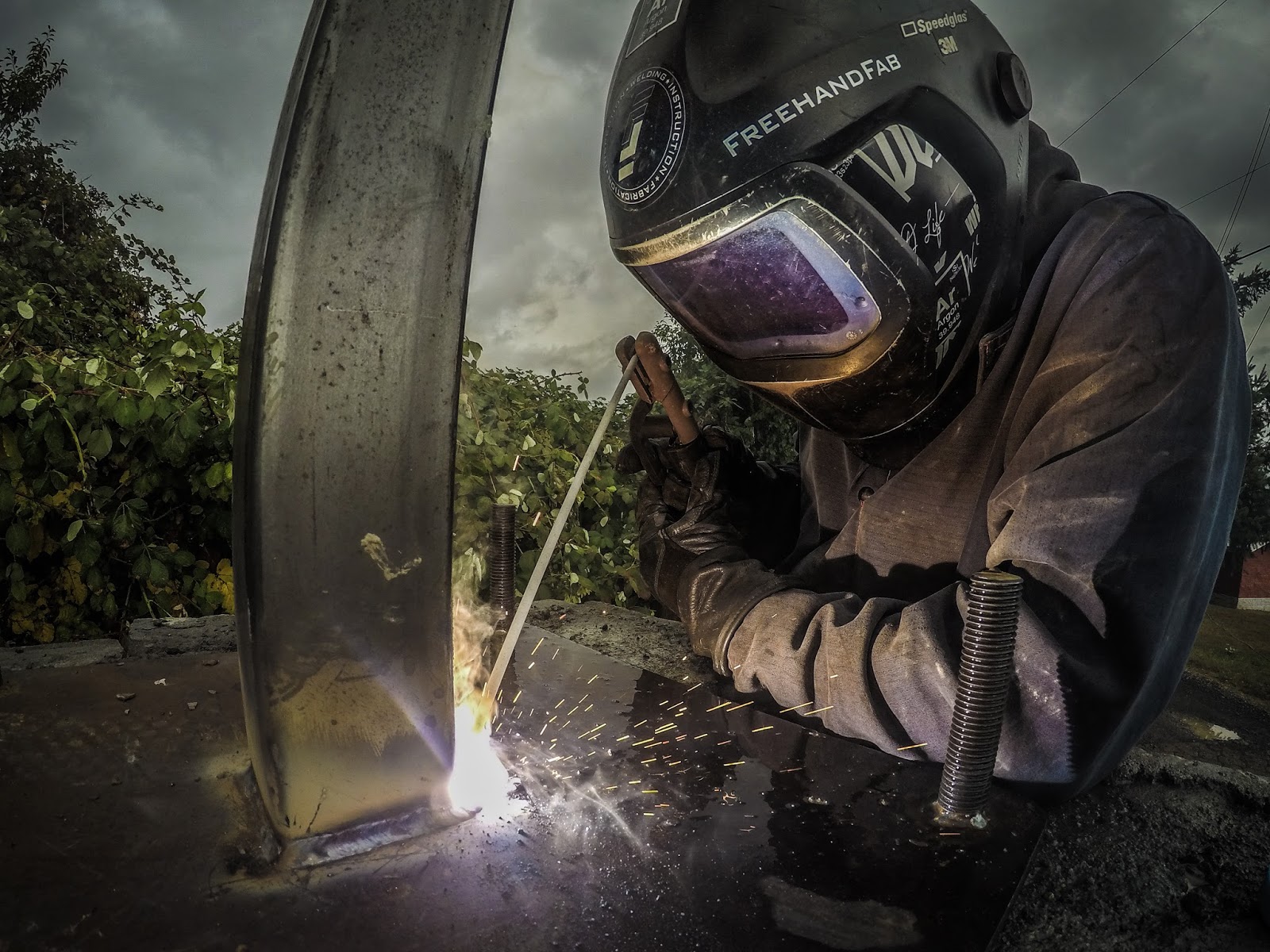
WELDING :
Welding is a process in which both the participating metals are metaled and re solidified to complete as one metal. Proper melting of mating parts is a basic criteria to result a sound weld.

BRAZING :
>In case of Brazing both the participating metals are not melted but a third metal of lower melting point is used to be filled in between the two. The solidification of this third metal results the joining.
>The filler metal is drawn into the gap between the closely fitted surfaces of the joint by capillary action.
>The design of the joint should incorporate a minimum gap into which the braze filler metal will be drawn.

Thursday, 1 February 2018
Lapping Machines
Lapmaster Wolters Single Sided Lapping Machines

Fundamental Lapping Theory
The basic theory of lapping starts with the components being placed within the confines of conditioning rings directly onto the surface of a rotating lap plate that is coated with a precision film layer of slurry. The components should never come into direct contact with the lap plate surface. Through powered lap plate rotation, the loose and rolling abrasive particles within the slurry layer transfer cutting energy with their sharp cutting edges by penetrating the contact surface of the components removing microscopic chips of material. Concurrently the abrasive is acting on the lap plate via the contact surface of both the components and conditioning rings causing wear that when controlled by adjustable radial ring position will effect spherical curvature changes to maintain a flat lap plate condition.
Lapping successfully: Factors to consider
- Type of material being processed
- Speed of plate
- Pressure on work-piece
- Plate material
- Size and type of abrasive
- Vehicle used
- Flatness of plate
- Feed system
- Method of charging and conditioning the plate
- Plate temperature
Peter Wolters AC microLine® Double Sided Lapping Machines

The high productivity double sided lapping machines of the Peter Wolters AC microLine® range display state-of-the-art design and concept. The modular system of main components together with the precision of the latest control-, drive and measuring technologies superb process reliability and make the system simple to operate. Easily removable machine linings and fully covered process areas give the best accessibility and industrial safety. For automatic loading and unloading, the upper wheel can be swung out.
Durability, reliability, low cost of ownership, variety in applications and automation solutions – these are the outstanding features which characterize every AC microLine® machine. For further increase of productivity, all machines can be equipped with automation setups. Choose between semi and fully automated versions. These automation choices guarantee optimal unit cost combined with high throughput and, therefore, the most economic solution.
The Lapmaster DSL series of double sided lapping machines are driven by three, variable speed motors for maximum process control flexibility. All three rotating machine components, the sun gear, top plate, and bottom plate, are independently controlled. Process down pressure requirements are pneumatically regulated and continuously monitored by a load cell.
Wednesday, 31 January 2018
Fine Grinding vs Lapping
What is Fine Grinding?
- Fine Grinding is a batch-mode abrasive machining process that combines the speed and aggressiveness of super abrasive wheels with accuracy of lapping kinematics to produce flat and parallel work piece surfaces.
- The cutting tool consists of an upper and lower wheel composed of diamond or cubic boron nitride (CBN) with different bond types (vitrified bond, resin bond or metal bond) and act as the support plates for the work pieces.
- The machine tool has evolved from the vertical double-wheel lapping machine design with a planetary work drive system, also known as “lapping kinematics”.
- In place of lapping wheels, grinding wheels are fitted and cooled through labyrinth in the working wheels and a coolant fed through holes in the upper wheel.
- Since Fine Grinding requires higher forces and uses higher cutting speeds, motors, gears and the rigidity of the machines are much stronger than lapping machines.
- Work pieces are guided between the upper and lower working wheel in an epicyclical path as defined by inner and outer pin ring, upper and lower working wheel, speeds and directions, while material removal takes place simultaneously on both sides.
FIne Grinding Technology
Definition of the Tooling Methods
- Lapping flat parts – single or double-side) is the abrasive machining process for removing material using a loose abrasive in a liquid mixture (known as a slurry) at low speeds.
- Loose abrasive is moving over the surface under pressure , will knead, abrade, chip or scrape away the surface of the workpiece . By exceeding the bending strength the material breaks out.
- Fine Grinding (flat parts – single or double-side) is the abrasive machining process for removing material using a bonded Superabrasive wheel at low speed with a liquid to keep the part cool. The fixed grain of a geometrically indefinable cutting shape acts like a plow and material is removed by micro-grooving /-cutting . The chip formation occurs by exceeding the shearing strength.
Kinematics of the Fine Grinding Process
Fine Grinding generally follows the same kinematic principle as lapping. The workpieces are held in carriers which are driven to describe a planetary motion covering the full surface of the Fine Grinding wheel. The drive mechanism consists of an inner and outer pin ring. The outer ring is generally fixed while the inner ring rotates in either the opposing or the same direction as the lower working wheel to create a series of epicyclic rotations.
Fine Grinding vs Lapping

Fine Grinding
- Performed with super abrasive (diamond or cubic boron nitride - CBN) wheels
- Stock removal caused by micro grooving / -cutting
- Fine-ground surface has cross-hatched marks
- Coolant is recycled
- Fine-ground parts are coated only with a thin layer of coolant and therefore only minimal workpiece cleaning is necessary
- Wheel speeds are typically 2 – 15 m/s
- 3 – 20 times faster than lapping (removal rate)
Lapping
- Lapping is a working process, during which workpiece and tool slide over one another on a loosely applied medium (lapping compound) and are subject to continually changing direction of rotation.
- Stock removal caused by rolling and sliding action of abrasive grains
- Lapped surface is dull and crater-like
- Material and lapping compound are not recycled
- Lapped parts are contaminated with lapping compound and require cleaning
- Lapping speeds are generally limited to < 1 m/s
Why use Fine Grinding?
General
- Accuracy results, previously only achieved by lapping
- The pellet structure allows a layout of the grinding medium, corresponding to the kinematics conditions
- Long and constant process cycles without dressing processes
- The space between the pellets allows a high flow rate of the coolant
- Very good chip flow without temperature problems
- High process quality, consistent repeatability of achieved values
- Also large surface work pieces can be machined
- Batch processing
- Work pieces are loosely held in carriers and therefore machined stress free (without distortion - especially for machining of thin or delicate parts)
- Work pieces of different shapes could be machined (i.e. round, rectangular or irregular; full surface or with cut-outs)
- Easily to be automated
Fast
- High removal rate using super abrasive diamond and CBN (3 – 20 times faster than lapping)
- Possible saving of pre-machining steps
- Long intervals between resharpening
- High flexibility
- Automated solutions
Clean
- Recycling of coolant
- Tremendous less waste than with lapping
- Minimal work piece cleaning necessary
- Reduced downtime
- Cleaning of work pieces without problems by rinsing; in comparison to lapping ultrasonic or chemical cleaning is not necessary
Economic
- High removal rate (reduces capital costs and personnel expenditure)
- Low wheel wear _ long life time of the grinding wheels (reduces the tool costs)
- Low waste disposal costs (reduces the current running costs)
- Low work piece cleaning costs (reduces the current running costs)
- Possible saving of additional machining steps
- Easy wheel maintenance _low tool manufacturing costs by using a “Standard-Pellet-Form”
Tuesday, 30 January 2018
hot and cold spark plugs explained

Introduction:
In order to ignite air fuel mixture we need heat.In case of diesel engines (compression ignition engines) this head is achieved by the compression of gases.But in case of spark ignition engines we need to have an external source to ignite air fuel mixture because compression is not enough to ignite the mixture.A spark plug is a device for delivering electric current from an ignition system to the combustion chamber of a spark-ignition engine to ignite the compressed fuel/air mixture by an electric spark, while containing combustion pressure within the engine.
There are two types of spark plug :
- Hot Spark Plug
- Cold Spark Plug
“Cold” spark plugs normally have a short heat flow path. This results in a very quick rate of heat transfer. Additionally, the short insulator nose found on cold spark plugs has a small surface area, which does not allow for a massive amount of heat absorption.


On the other hand, “hot” spark plugs feature a longer insulator nose as well as a longer heat transfer path. This results in a much slower rate of heat transfer to the surrounding cylinder head.
The heat range of the spark plug must be carefully selected in order to create an optimal thermal performance. If the heat range is not correct, you can expect serious trouble. Typically, the appropriate firing end temperature is 900-1,450 degrees. Below 900 degrees, carbon fouling is possible. Above it, overheating becomes an issue.
Subscribe to:
Posts (Atom)